
If you are a bridge engineer and you hear the term “negative filet,” you typically start shaking uncontrollably. It’s one of those natural reactions when your senses tell you that Something Isn’t Right.
In this post, I want to explore negative fillets, and more specifically, bridge parapet overhang negative fillets. It is a concept that everyone involved in the bridge building needs to understand but few really do.
What is a Bridge Deck Fillet?
So go ahead and Google “Bridge Deck Fillet” and see what you get. Go ahead. I’ll wait….
Wow. Surprising, isn’t it? There’s not a whole lot of basic information to be had out there. Refer to my previous post on Blog Competition: this just reinforces my point.
So for the beginners out there, I think one of the best practical references available is the Caltrans Bridge Deck Construction Manual (LINK HERE). I encourage you, if you are a novice, to explore this resource and educate yourself on terminology & the how-to’s that they present.
Let’s jump to looking at fillets. A bridge fillet is basically a “stool” of concrete that is in-between the top of the beam/girder and the underside of the concrete deck.
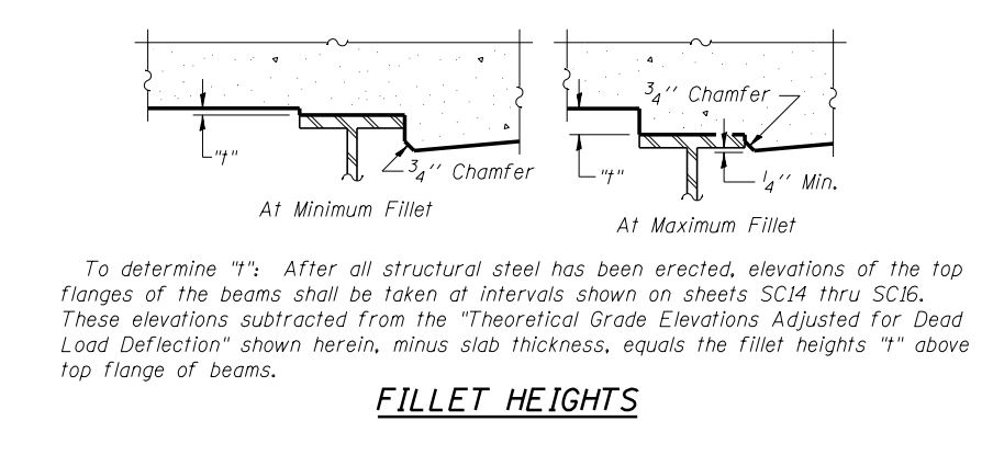
The depth of the fillet “t” varies due to 3 criteria:
–The actual elevation of the top of the girder in its “un-decked” condition
–The amount of deflection that the girder will drop when the concrete deck is cast (called “Dead Load Deflection”)
–The proposed elevation of the top of the deck after concrete is cast

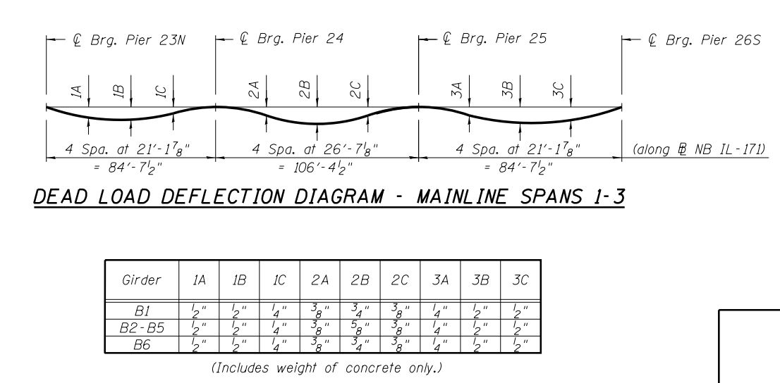
The bridge design engineer will develop the deflection information to be used in constructing the deck, both in general profile for each girder & span and in table format:

So, to use this data and set the bottom of the bridge deck, the unloaded girders are shot for elevation at the defined locations in the deflection tables. This allows the height of the “stool” to be calculated so that, when the deck is cast and the girder is exposed to the wet/dead load of the deck, the finished surface of the deck is in the proper location.
What Happens When the Fillet < 0″
Occasionally an engineer will run across the condition known as a “negative fillet” which is when the “stool height” is actually < 0″. This essentially says that the top of the girder is too high to accommodate the proposed elevation of the top of the deck ie. the deck is going to be thin over the girder. This condition typically occurs in bridge redecking or rehabilitation projects when the girder has morphed from it’s original camber, or, where the design engineer is attempting to modify either the longitudinal or cross section parameters for the deck whereby the proposed deck thickness may not be accommodatable given the condition of the girders. It’s rare, but it happens.
And now we get to the crux of this post:
Bridge Parapet Overhangs = Negative Fillets
OK, so let’s take a look at the outsides of the bridge deck – the parapet overhang.

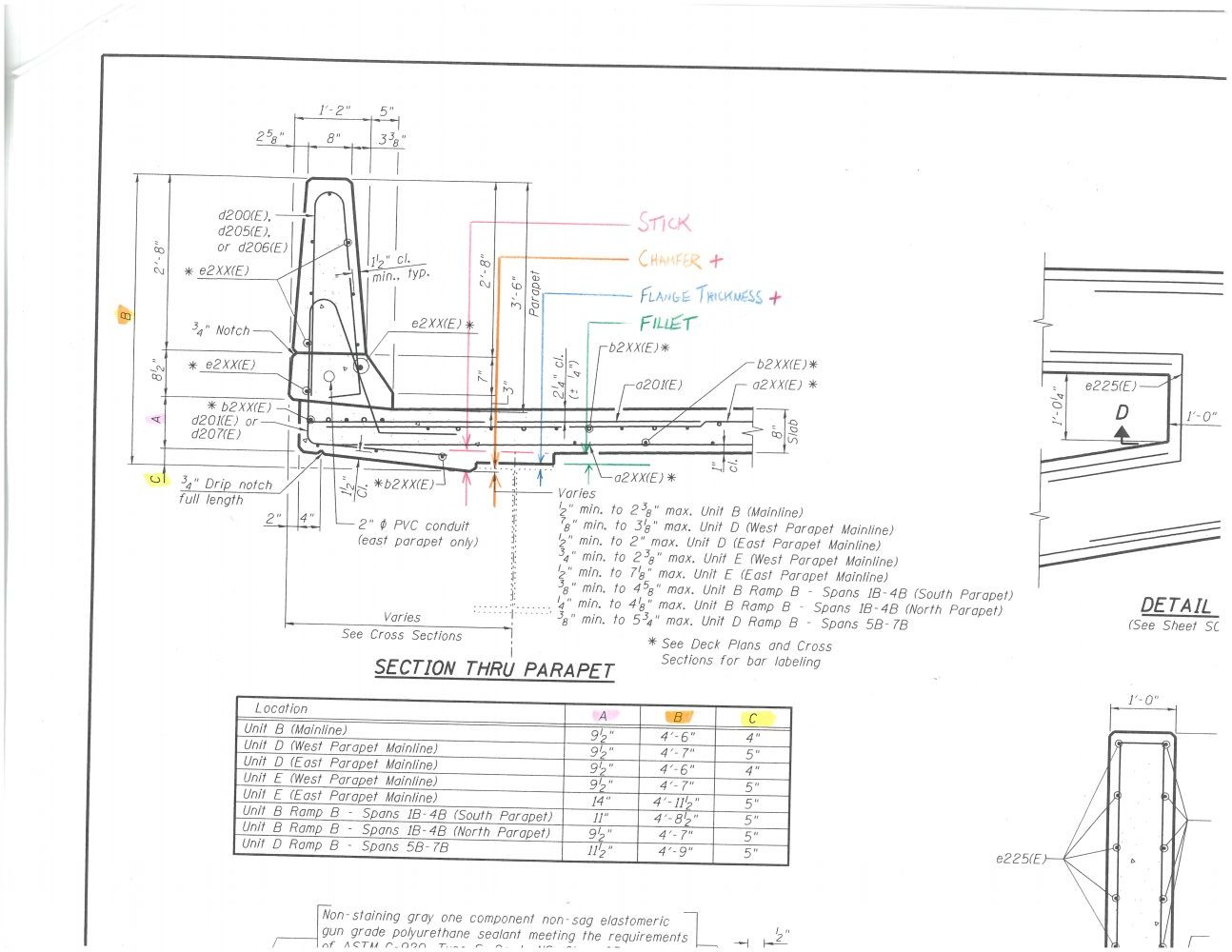
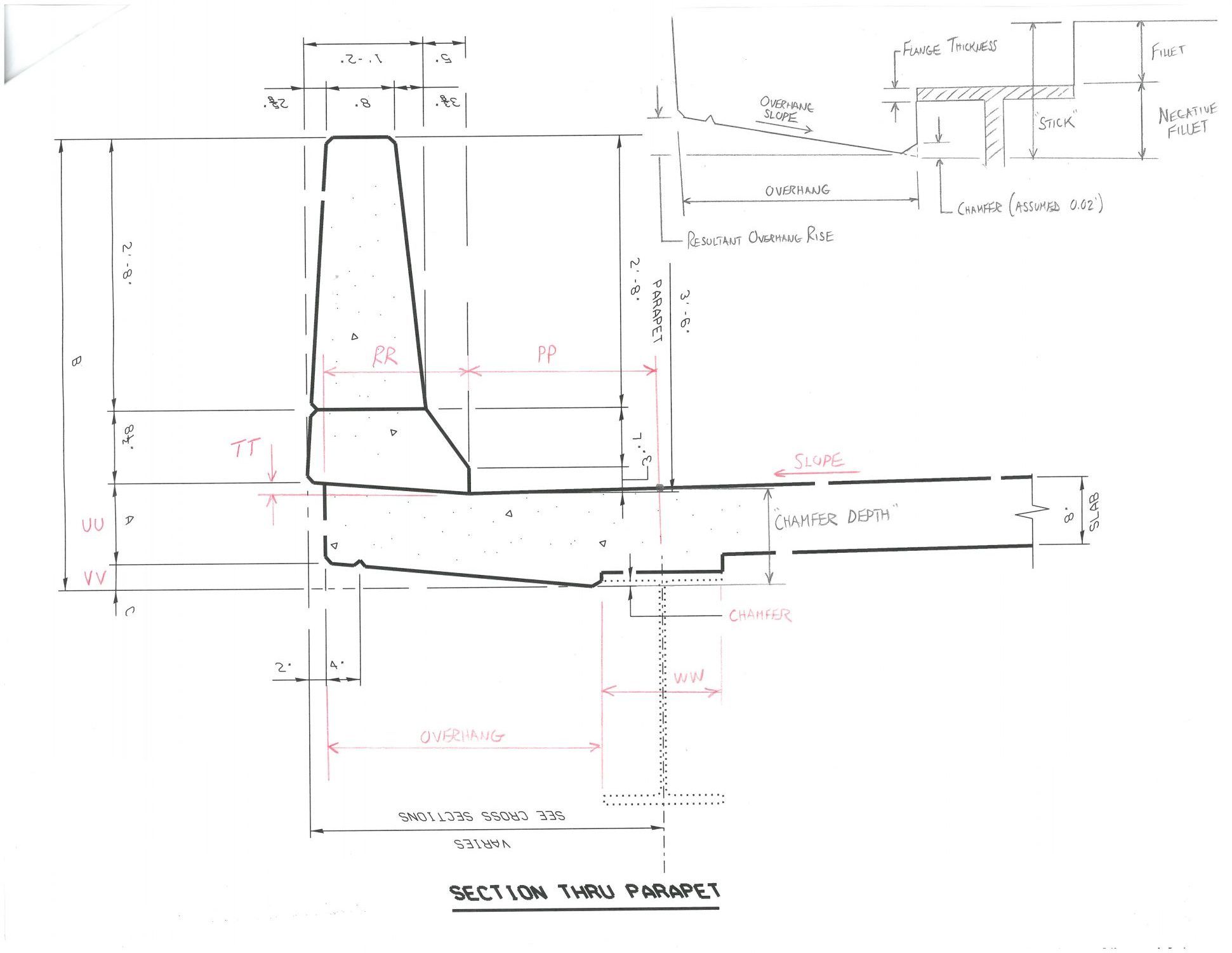
If you look at the bridge deck cross section, you’ll notice that the outside of the deck has a thickened edge condition. This thickening, in typical Illinois DOT bridge designs, accommodates the additional reinforcing and mass concrete that allow the parapet to withstand a vehicular impact. The overhang typically has a back-pitched underside, called the “water table”, which allows condensation and runoff from the back side of the wall to be channelized in a drip notch, preventing the water from dripping & draining onto the fascia girder.
As you look at the detail, below, you’ll notice that the parapet overhang is below the top flange of the girder. By our definition, this is considered to be a negative fillet. At first glance, you might think that the dimension of this negative fillet is a constant, given its presentation in the detail & its general shape. Unfortunately, that isn’t the case. And calculating this varying dimension can be a very arduous calculation. Let’s take a look at how you do it.
Introducing the Concept of “Stick”
I was introduced to a bridge construction concept that I had never heard of in 25 years of building roads & bridges. I credit Chris McGann, one of our company’s senior engineers, for showing me the ropes. It is not an easy concept to grasp without really having a good understanding of bridge deck construction, beam deflection theory & general fillet calculation methods. To learn this calculation method is most-certainly a 200-level bridge construction class, but once you “see” the concept in action, it will make sense to you.
The excerpts I’m using in this post are taken from the current bridge rehab project that our crew has been working on this past year. For our project, the bridge design engineer specified varying parapet overhang dimensions as can be seen as dimension “C” in the table.
We know that the fascia girder will have camber in it, so that will generate variations in the top-of-girder elevations that will force variations in the anticipated fillets.
Now, consider that the bridge profile is basically a flat surface – of course it has cross-slope and a longitudinal slope component, but for sake of discussion, let’s call it flat. The deck position will, of course, drive the final location of the top-of-parapet and the edge-of-deck, which is what your eye will see when you look at the outside of the bridge, and accommodation for the dead load deflection of the cambered girder. This drives the need for the final vertical position of the overhang to vary with the same magnitude that the fillet “stool” does, but, its variations are going in the opposite direction of the fillet “stool” – the fillet is an “up” dimension while the overhang is a “down” dimension.
Go ahead and re-read that a few times so it sinks in. It’s confusing. And it took me a while to digest it too!
Think of it this way: Our desired outcome is for the outside edge of the deck to fluctuate similar to the fluctuation that is occurring at the fillet “stool.” That’s where the term Stick comes in.

The Stick is a term given to a steady dimension that combines 3 dimensions:
–The fillet “t”
–The thickness of the girder/beam flange
–The overhang “rise” or “negative fillet” that is driving the parapet overhang depth
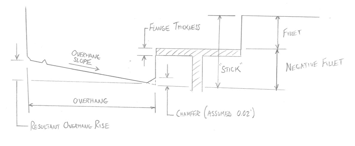
Try to envision the concrete deck on top of the girder flange in the picture: As the proposed top of the deck moves up and down over the flange, the fillet will be varying up and down. This will force the outside of the deck at the overhang to also want to vary up and down. All of this up-and-down variation is happening within the guts of the bridge, but the end product, which is the edge-of-deck and the top-of-parapet, are following the bridge profile. The sight lines and bridge surface are smooth, and that is driven by the relationship of the fillet+negative fillet which are floating up and down over the cambered girder.
Makes sense right?
Picture this: You have a highly-cambered girder:
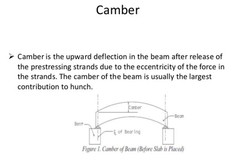
CREDIT: http://www.slideshare.net/Mahfuzcv/shear-bond-bearingcamber-deflection-in-prestressed-concrete
The dead load deflections at the piers are 0″, vary within the span, and are at a maximum mid-span. If we assume that the finished bridge deck is designed to be flat, the fillets will be at their maximums at the piers and at their minimums at the mid-span. Since the “down” negative overhang fillet is working opposite of the regular “up” fillet for the stool, we need to make sure that the we do not have an “up” fillet that is so tall that it pulls the “down” negative fillet above the top flange of the girder. We need to, therefore, select a Stick dimension that optimizes the fillet height AND makes sure that a negative overhang doesn’t occur.
Confused? Don’t worry: I was, at first too….
Let’s dig into the calculations and it will start making sense for you.
Calculation Methods
There are 2 ways of calculating the Stick that will determine the overhang negative fillet dimensions.
1. The Maximum Fillet Method
One way of calculating the Stick is to look at several factors related to a span:
- Actual Fillets
- Flange Thickness
- Chamfer Strip at the edge of the girder flange
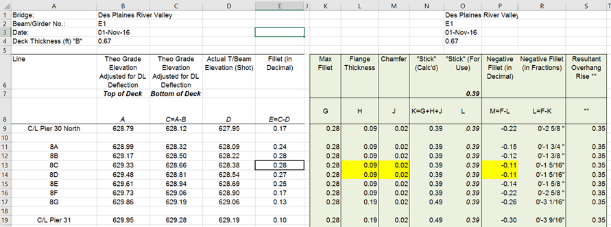
Let’s review the calculation table. In Span 8, the fillets vary from 0.10′ to 0.28′. If the fillet is in its maximum “up” position, this is our critical fillet. At this location, the negative fillet should be at the minimum “down” position. So if we add the maximum fillet + flange thickness + chamfer strip (1/4″), we get a calculated Stick dimension of 0.39′.
By using this Stick value and re-calculating the negative fillets you’ll see that now, the negative fillets for the overhang will vary from pier-to-pier. The negative fillet, as expected, is minimized at the mid-span and maximized at the piers. The negative fillets (calculated in Column R) become the “down” dimension for the span. And the negative fillet will be tight up against the girder top flange at the midspan locations 8C & 8D, but they never become higher than the girder flange.
This method of Stick dimension selection is not simply a mathematical analysis: The construction engineer needs to review ALL of the dimensions within a span, or multi-span unit, and select a Stick that optimizes minimum fillets with overhangs. It takes some practice and intuitive analysis, but once you gain confidence in using the method, selecting the Stick is a relatively simple process.
2. Around The Horn Method
When Chris introduced me to Maximum Fillet Method, it took a while for my brain to process it, given the “intuitive” nature of the analysis. You have to be able to look at the entire bridge unit, fillets & flange thicknesses to, kind of, “massage” the right Stick out of the calculations. So, being more left-brained & wanting to better-solidify the calculation methods in my head, I developed a 2nd way of developing the Stick , using a more mathematical means.
I dug back into the unused tools in my toolbox and grabbed some Static Equilibrium theory principles, and instead of summing forces around a mass, I just summed dimension around the girder, allowing the resulting Stick dimension to be driven from summing X & Y coordinates around the deck edge:
In tabular form, it looked something like this:

I used this table as a check-and-balance against the more-intuitive Method #1. It works very well, but its output wasn’t taken to be the final answer. Here’s why.
One thing you’ll notice is that the Stick calculated is 0.46′, larger than the 0.39′ we developed in Method #1. That’s because Method #2 does not allow for an optimization of the negative fillet like Method #1 does, it is simply a mathematical summation of the X & Y coordinates that generate a “mathematical Stick .” Look at the mid-span negative fillet, which is 0.17′. That means there actually is additional overhang concrete framed into the deck, instead of Method #1, where we optimized the negative fillet to force the overhang to be at its minimum at the midspan.
Bottom line: The Stick of 0.46 will work fine, it will just generate the need for additional concrete in the parapet overhang. If the construction engineer wanted to optimize the volume & weight in the overhang, the comparison of the two methods can be used to drive an optimal dimension.
Summary
Stick is a difficult concept to understand. It took me, a seasoned construction veteran, a couple of days and several iterations of spreadsheets to understand it. Take time to understand the mechanics of the calculation methods and principles when doing your assessments and before too long, you’ll be a wiz at it.
If you need some help with the concept, feel free to hit me up with a comment or an email, I’ll lend you a hand.


Dear Bob
This is Prithiviraj from India an novice but passionate Civil Engineer, got somewhat from the article regarding fillets but the stick calculations are yet to be cleared. Please share the spreadsheet in my E-Mail to go through the subject in depth further for better understanding.
Thanks